1. Sycamore
This is a new project for this winter (December 2021) and the idea is to make a tall lamp stand from a curvy pole/branch of green wood such as hazel, sycamore or ash. It may be a multi-stand with several poles from one base or a single pole, I am not sure yet and will see how things progress. When I've seen this before, the poles are cleaved from a large log of wood, e.g. sycamore or sweet chestnut, and then shaped as needed much like I did with the legs of the tall ash stool described on another post. I am going to try and do them from a single branch or main stem of smaller diameter. At the moment I can't see anything on the internet that describes doing this so it will all be trial and error!!
 |
| Green sycamore pole about four foot long (128 cm) and 2 inches diameter at the top and 3 inches at the bottom. |
I now have a four foot long (2 -3 inch diameter) green sycamore pole shown above and felled 3 days ago, that I will use to test methods etc and a local craftsman is soon getting some other poles of hazel and ash from a hedge he is managing. Meanwhile I will try out the methods on the sycamore pole. The lampstand needs an electric cable down the centre, eg. twin flex or similar, and the only way I can see to do this is to cleave the pole down the centre and then carve a channel for the flex to lie in and then glue the two pieces back together with the cable inside. I tried this with some small hazel sticks (3 cm diameter), cleaving them and trying different glues. I found that neither PVA (white glue) or Cascamite held even after 24 hours but that Evo-Stik polyurethane (PU) adhesive did work. I glued these with the bark on and after the glue had set, I stripped off the bark and had difficulty seeing the join in the wood. These were left to dry indoors for a week and have remained intact. The main lesson from this is that the glue needs to be applied over as much of the cross section as possible so I need to figure a way to keep the cable inside the core groove.
I next tried the same method on a short piece of the sycamore pole. This was cleaved easily and a channel to house a cable carved with a gouge. The two pieces were immediately joined with the PU, clamped as shown below and left for 24 hours to set. The bark does offer some protection to the underlying wood whilst the clamps are in place.
 |
| The sycamore pole after gouging and rejoining. Note that the centre of this wood is infected. The PU glue dries and expands so the wood has to be tightly clamped. The dried PU is easily removed when the joint is dry. |
 |
| After joining and stripping the bark off. A very thin line of the joint can just be seen. |
After this I tried another glue referred to as "Hide Glue" purchased from Timberline. This is a protein made from cow hide and the glue we used in woodwork classes in the 1960's. I used 192 gram strength which is recommended for general wood working. The higher the strength the stronger the join but faster settings as the protein polymers are longer at the higher gram strengths. I refer to the excellent video by Bob Rozaieski (https://brfinewoodworking.com/?s=hide+glue ). An advantage of this glue is that it is a natural glue and is reversible by heating the joint to about 60 C. The joint isn't waterproof but the glue was widely used in furniture making and so now enables some old furniture to be repaired without damaging joints. I thought it would be interesting to try the glue for the lampstand. My first attempt with hazel sticks was not successful mainly because I mixed the glue too thinly. I tried another attempt using a 1:1 by volume mix of the granular glue (basically a coarse powder) with water. This seemed to behave in a similar fashion to the demonstration of Bob's near the end of his video. I wasn't sure whether the joint would hold as the wood is very green. However, I clamped it and left it overnight but in the morning it had weakly bonded but not enough for this purpose. The wood needs to drier before I can use hide glue.
Having decided on a suitable glue, I then cut the pole into two pieces about 65 cm long, stripped the bark off and then made a cylindrical tenon on the bottom. This was just over two inches long and made so that the join to the stand was 1 3/4 inches diameter. I found this was straight forward by using the fine bladed kerfing saw to cut around the end of the pole and then chisel-out the shoulder. The end grains of the pole were then sealed with wax.
 |
| Pole stand with the tenon cut on the base. |
 |
| Cap of beech made to fit the top and for mounting the lamp holder base rather than to screw the base into the end-grain of the pole. |
After 3 weeks in the workshop I decided to try cleaving the pole using a froe and homemade brake. I started at the lampholder end to get the split in the centre and chose a line that avoided hitting knots head-on, This worked fine by making adjustments and putting pressure on the wide part of the split if it strayed too much. The cleave was clean and left some pith in the middle.
 |
| Showing the froe moving down the pole to make a clean split in the centre. |
 |
| The two halves of the pole with the the channel for the electric cable gouged down the centre. |
 |
The pole with the cable installed, glued and clamped.
|
The channel down the centre was gouged using a small gouge (about 8 mm across and one I brought back from India and purchased at an outdoor market and duly sharped). The depth of the channel was checked with a vernier set to the diameter of the cable. The cable exited at the bottom about 1 inch from the top of the base
via a 5/16 th hole as shown. Sufficient cable was allowed at the top for the lampholder mounting. The pole was glued with polyurethane adhesive (tested above) and clamped as shown. This was done by clamping the lampholder end and then the other end was clamped loosely being careful to align the halves, Then the rest was clamped starting from the lampholder and moving down, making sure each clamp was tight and the halves aligned. The assembly was then left overnight to set.
After a further 2 weeks drying, I sanded the stand with 180 grit (across the grain around knots) and glued the beech cap in place.
 |
| The beech cap glued and clamped after detailed sanding of the stand. |
I then purchased a 40 mm thick kiln dried plank (1.13 m x 0.3 m) for making the base and drilling the mortice to accommodate the lampstand.
 |
| The kiln dried sycamore (The Scottish Wood Shop) used to make the lampstand bases. This is 40 mm thick and will be used to make other lampstands. |
I sawed off a 19 cm section of the sycamore board and planed it to remove the dead cambian and generally tidied it up. I then found the best place to mount the stand and drilled a hole 45 mm diameter to match the bottom of the stand.
 |
| Irwin adjustable drill used to drill the hole in the sycamore base. |
 |
| Drilling the hole in the base to mount the lampstand. |
Next I mounted the stand by adjusting the fit with a chisel/carving knife and making suitable channels in the tenon of the lampstand. I used a divider to mark around the base of the stand to get a good fit to the base and then carefully sawed and chiselled this edge. Incidentally, this is a trick I saw on one of those Alaska cabin build programs where they use a scribe to mark the logs to enable them to fit snugly together! Originally I thought I could put the cord through without extending the channel in the tenon to the base but this proved difficult (I tried this on a test piece). So in the end I decided to put the flex in a channel gouged in the cylindrical tenon extending to the end. This enables me to gradually put the tenon in place, adjusting the fit as necessary, and also getting the join to the base a good fit using the scribing method I described and cutting with a fine tenon saw and chisel. Unfortunately I had forgotten to orientate the lampstand so that the curvature went towards the front of the base and so add to the stability of the stand. This meant that I needed to direct the flex through 90 degrees making a channel going round the tenon before going down the tenon to the exit hole, This worked out OK and I was able to hold the flex in place using insulating tape (subsequently I made a deeper groove that held the flex better and didn't need the tape). I also carved an internal sloping channel going down to the exit hole to ease the exit of the flex from the channel in the tenon to the hole in the base.
 |
| The electrical lead was channelled in the tenon ready for inserting into the hole in the base. This does leave a small hole in the base after the stand is fitted. This will be plugged to give a neat finish. |
 |
| Drilling a 3/8 inch hole for the electric lead to exit through the base. |
I then used the PU glue to fix the stand into the base and left this clamped overnight to cure.
 |
| This is the lampstand after glueing and sanding but before treatment with danish oil. |
 |
| After treatment with danish oil and macrame shade. The sycamore pole has darken a little but is still lighter than the older sycamore base. |
Notes on improvements.
1. Is there another way to fix the lamp fittings on the top without needing a cap? ( yes, see the method developed below)
2. Spend more time shaping the stand after glueing. In particular, making the top narrower. Choose suitable shapes for the stand(s). ( yes, this can be done with the wood still wet and finished after it has dried)
3. Check the orientation of the flex exit in relation to the exit hole in the base to avoid having to curl the flex around the tenon.
4. Try and plan to have the join at the sides of the lampstand rather than in full view at the front. This means planning before cleaving to get the join in the right plane and also the bend of the lampstand itself facing the right direction.
2. Ash
My next attempt was with a small ash tree that had been felled from a Dartmoor coppice. It had the early signs of ash dieback; all the ash trees in the coppice has suffered the same fate.
 |
| The stem having removed the bark, cleaved and gouged the channel for the electrical cord. |
The bark and side branches were shaved off and the stem cleaved down the centre. The wood was fibrous and did not produce as clean a split as the sycamore. Anyway I continued with the gouging and glueing using as many clamps as I could fit in !
 |
| Clamping after applying the PU glue and leaving to dry overnight. |
After drying, the stem was shaped using a small draw knife and spokeshaves to produce a curved and tapered lampstand. Most of this shaping was around knots from side branches and I found the best method was to shave to the centre of the knot from both sides and try and match the shape of the main stem. I found the miniature Moro drawknife and a small wooden spokeshave were best for this task.
 |
The curved lampstand in preparation. The vice and wooden clamp allowed me to stand and work on the stem. I could have used the shavehorse but this was a convenient method of working whilst standing. This is a long curvy pole so should be a good candidate.
|
Also made a second ash stand, this time shorter (66 cm) and thinner (from 4.2 to 3.5 cm) but with a patch of dead wood.
 |
| Second ash stand. |
This was also left to dry in a cold workshop for two months before further working.
3. Hazel
I had collected several trunks of hazel wood from Dartmoor (thanks for the help of James Dyson from Totnes) with diameters between 5 to 15 cm. They were all slow grown in shade conditions and had twisted trunks to varies degree. I had tried one of the shorter and smaller ones by shaving it to size but when I tried cleaving it, the split ran out because of a twist in the stem. I then tried one of the longer (180 cm) and larger girth ones (roughly 12-15 cm) and managed to split this in half with the aid of iron wedges. However, the split was not very clean with a lot of tear-out and did not look promising for further cleaving to a smaller diameter. However, I continued with the preparation by cleaning up the splints and removing the bark. Also I tried another method of mounting the lamp connection. This involved drilling an insert into the end-grain of three diameters. The top hole was 26.8 mm diameter (about 1 1/16 inch auger) and 5 mm deep, followed by a small diameter of 15.2 mm (about number 10, 5/8 inch) to 5 mm and then finally for the threaded stem of number 6 (3/8 inch drill) to a depth of over 25 mm to allow the thread to be screwed into the hole. This allowed the brass fitting to be inserted into the top.
 |
| The brass lamp connection with a 1 inch long 10 mm threaded pipe to be connected to the end grain at the top of the stand. |
 |
| The large trunk ready for cleaving. This proved beyond my ability!! |
In the end, further cleaving proved too difficult because of the twist and run-out of the split. Also the split was far from clean with lots of tear-out and in some places multiple splits. Anyway failure leads to knowledge and I concluded that this type of hazel is difficult to prepare.
Next I tried another trunk of hazel that was about 6-7 cm in diameter and about 170 cm long. This time I decided to cleave the length with the bark on as the piece had bends and a twist so I wanted to keep the full width to enable the split to wander a little without running-out. Also I tried drilling the holes on the top ready for mounting the lamp connection (shown above).
 |
| The hazel stem showing the lamp connection hole at the top. This was drilled in the centre prior to cleaving. After cleaving the hole needed to be connected to the cord channel running down the centre. |
The electrical cord channel was then gouged with care to connect this to the hole near the top. The PU glueing proved to be challenging and an extra pair of hands would have been better! The problem was the twist and bends in the stem and getting the halves aligned after glueing and before tightening the many clamps. I later developed a more systematic method of glueing and clamping as shown below.
 |
| After clamping. This really needed more clamps than I had at hand because of the length of the stem. Note that the bark remains on at this stage. I found it difficult to clamp smaller diameter lengths. |
After leaving overnight to set, the bark was removed and the stem shaped with a drawknife and spokeshaves, The top was reduced in diameter to match the lampholder (about 35 mm) with the cord in the centre. A threaded pipe for mounting the lampholder was then screwed into the pre-drilled hole in the centre leaving a protrusion of the thread of about 10 mm. This proved to be a tight fit and hopefully it will tighten further as the wood dries.
 |
| The lampholder threaded pipe mount screwed into the centre hole. |
 |
| The lampholder after screwing onto the threaded pipe. After the wood has dried, the top will be finally shaped |
Another hazel stem was then selected, this time with a single gentle curve and shorter than the others. This was cleaved with the bark on and then the mounting hole for the lampholder was drilled as described above. The cord was put in place and the stem glued and clamped being careful not to put too much glue near the top so as to keep the mounting hole clear. The next morning the stem was shaped as before and the threaded pipe screwed into place. I found I needed about 50 mm of electrical cord protruding from the top of the wood to allow the connections to the lampholder.
 |
| The second hazel stem after it was roughly shaped to size. |
 |
| The three stems with cords and lampholders in place. These will be left to dry in the unheated workshop for about three months. |
Also did another hazel stem and this ran-out close to the end but this was useable. It is not always easy to guide the split when there is some twist in the trunk.
 |
| Showing the cleaving action. It is not always easy to guide the split. |
 |
| The centre core ready to receive the electrical cord. I found this the best method of holding the work so that the centre core is held in the vice facing upwards, the gouging is then done and flex put into place. The glue is then applied and spread on this face only and then the top half is clamped into position. Finally the piece is rotated in the vice to enable further clamping. |
I found the best way to make the centre trough for the electrical cord was to use a large 15 mm gouge to start with and then a gouge with a smaller width (8 mm) to get deeper. Then with this clamped above the bench and cord in place, glue was applied and spread. Then top section was clamped into place with about 150 mm between clamps and left overnight. When possible, the clamped length was further clamped in a vice by rotating the stem and applying further pressure.
A further hazel stem about 180 cm long was made. This one had a curvy top and should make a nice lampstand. So in total I have four hazel stems and two ash ones that will be left to dry until the beginning of April (about two months).
 |
| The two hazel stems left to dry. |
Wood Treatment.
I wanted to use shellac but had found that with this ash and hazel wood that it did not impart enough colour. I then tried some alcohol based aniline dyes mixed with shellac.
a) Dartfords "Golden Oak" dye. This gave the wood too much of an orange colour. Deeper than the garnet shellac.
b)Dartfords "Medium Walnut" dye.
c) Dartfords "Brown Mahogany" dye.
d) Dartfords "Metal Complex Wood" dye
Also at this stage I decided to mix my own shellac using products from Rothko & Frost. I started with Liberon Garnet flakes making a "1 Lb cut" and dissolving using their alcohol solvent (also used for the aniline dyes).
So for a "1 Lb cut" this is 24 g of flakes in 200 ml solvent, 12 g in 100 ml, 6 g in 50 ml and 1.2 g in 10 ml. For stronger "cuts" the amount of flakes is increased in proportion, e.g. for a "2 Lb cut" it is 48 g of flakes in 200 ml of solvent. Also some woodworkers recommend "1/2 Lb cut" to start with, i.e. reducing the mass of flakes by one half. Originally a "1 Lb cut" was 1 pound weight in 1 gallon of solvent alcohol, so I have just reduced the volume as once made-up, shellac may only keep for 6 months depending on the storage conditions. I found that the "1 Lb cut" dissolved in a couple of hours but I left it overnight to ensure it was fully dissolved. The solution was a deep brown cloudy colour.
a) Garnet flakes ("1 Ib cut"; I made up 10 ml dissolving overnight) produced a brown-orange colour on the hazel and ash. Less intense than the "Golden Oak" dye.
b) Button flakes also a 1 "Lb cut" were slower to dissolve but did so overnight. The hazel only showed a slight orange colour very much less than the garnet but didn't change the wood's colour much.
Best option is to try the dyes with the garnet shellac.
 |
First results from using the dyes. From left to right: Golden Oak, Yellow Metal and Medium Walnut. The wood at the top is pine and below, hazel.
|
The Golden Oak and Yellow Metal were too yellow by themselves and I don't think they would help with the garnet shellac. The Medium Walnut gave a grey tinge, especially with the hazel.
 |
| The top pine shows Brown Mahogany and then two shellacs with the button and garnet (last on right). The hazel also shows the Brown Mahogany but only the button shellac (fairly clear). |
So far the Brown Mahogany looks most promising and I will try a test with the garnet shellac. It will be difficult to judge without a full treatment and the effects of the final coats of danish oil.
 |
| This is a test strip of pine treated with 1 Lb garnet shellac and some Brown Mahogany added drop wise. Starting from the left, this is one treatment, two treatments etc to the final strip with five treatments. This was then given two coats of Wilko danish oil. The shellac seems to block the dye. The background is a table top made from beech. |
Each type of wood and even in the same species, the colour development and finish may be different. However as a first stab, I tried a test with a piece of pine using the garnet shellac as described in the photo legend above. It is difficult to prepare a known concentration of the Brown Mahogany dye because of the small amount of dye powder that is needed to make a solution. Although the dye concentration is arbitrary, the colour development with each treatment is clear although there is no difference between the forth and fifth treatments. The wood was lightly rubbed with fine steel wool between treatments. The whole length of wood was then treated with danish oil and left overnight to dry. I noticed that the drying time for the strips that had been treated four or five times was much longer than the other strips but all were dry after overnight at 19 C. A second coat of oil was applied and seemed to dry faster after about 8 hours (see photo above). These results indicate that it is possible to apply danish oil over shellac to improve the look of the finish. Theoretically shellac seals the surface so that the drying oil cannot interact with the wood fibres and dry so I'm not sure why I have had success.
After the lampstands had dried for just over a couple of months there were a few places where the stem had split open a little but not on the glue joint that needed attention and one possible solution was to use the garnet shellac mixed with the fine dust to make a filler that matched the hazel or ash. I first tried this on a piece of waste hazel sanded to 240 grit and treated with the shellac-hazel dust filler. This did not work as the garnet shellac was adsorbed to the dust particles to give a dark brown colour (to be expected as the exposed surface area of the dust is very high compared to the surrounding wood surface.) I tried some button shellac but the result was similar (slightly lighter) and also wood glue but again this gave a dark surface. I also tried some polyester resin with sawdust but this also produced a dark infill. The most successful method was using a standard white wood filler that did take the dye colour.
I then continued some test with colouring the wood using the aniline dyes. I found that increasing the dye strength in the shellac did not work as the shellac sealed the wood and it was impossible to get an even finish. This also meant that it was difficult to add second coats of the dyed shellac as the dye could not interact with the underlying wood. I then decided on a different approach using the dye alone in alcohol to dye the wood and then finish/seal with either shellac or danish oil. I first mixed a concentrated dye solution in alcohol (1 teaspoon of dye to 100 ml of alcohol). For this I tried both the brown mahogany and the golden oak dyes but found the golden oak gave too yellow appearance. The brown mahogany gave something closer to what I am looking for. I left this overnight to dry, lightly sanded with fine steel wool, dyed some of the wood again and dried before lightly sanding and finishing with either button shellac or danish oil. The conclusions from these tests were:
a) two treatments with the mahogany dye gave too dark a colour.
b) the treated wood produced different colours with the two finishing coats. The danish oil finish gave the wood a grey weathered colour. The button shellac produced a brown colour that might be expected for mahogany. Hence the shellac treatment wins although I have yet to see the effect of danish oil over shellac (even though drying might be a problem!)
 |
Treament of some hazel waste wood with the brown mahogany dye in alcohol (1 tsp in 100 ml of alcohol). Top left: two treatments of dye with button shellac finish. Top right: one treatment of dye with danish oil finish.
Bottom left: one treatment of dye with shellac finish. Bottom right: one treatment of dye with danish oil finish. The conclusion from this is that the dye is too concentrated and that the danish oil finish does not bring out the brown colour of the mahogany and gives a slightly grey tinge to the wood. |
As one treatment of the dye gave too dark a colour, I next tried diluting the alcohol/dye by two, i.e effectively one teaspoon to 200 ml of alcohol. This didn't work well and I have come to the conclusion that the grain structure and knots makes any dye application prone to an uneven and streaky appearance. Hence as the dye with shellac didn't work on this project, I returned to the idea of applying the garnet shellac alone and in multi-coats to bring out the rich colour.
 |
| The short hazel stand after applying several coats of garnet shellac. The surface gloss can be removed by using 0000 steel wool. |
The best lampstands were chosen, one ash and two hazel. The ash was intermediate in length between the two hazel lampstands. The poles were smoothed using the card scrapers followed by sanding with P80, P120, P240 and P320 grit Abranet strips. I found that using dyes/shellac shows any scratch marks etc on the wood surface so the final fine sanding is important. The tenons on the bottom of the poles were then cut out using a tenon saw, chisel and finished with a fine wood file. The final adjustment to the diameter and depth of the tenon will be done once the base is drilled.
 |
| A cylindrical tenon cut on the bottom of one of the hazel stands. |
The base was cut from a piece of sycamore (about 30 cm width and 50 cm long) and shaped. The holes were drilled for the stands by trying different orientations. An adjustable Irwin auger was used to drill the holes in the base.
 |
| The top of the base with the largest hole in front for the shortest lampstand. This will be treated with shellac once the stands are fixed into place. The orientation of the stands on the base were marked on the stands and the base. |
The underside of the base was made so that the individual lamps could be wired to a junction box set in the base. This involved cutting individual channels to accommodate the electrical flex to the junction box and also a channel for the flex connection from the junction box to the mains.
 |
| The underside of the base with the junction box in place but the channel for the mains input to the box not yet cut. The base will be covered with sheet of cork. |
Meanwhile the stands were further treated with the hope of getting a nice colour but still showing some of the grain detail.
 |
| Adjusting the stand angles on the base. The base is not finished yet and the stands are still being treated. So far about six treatments with garnet shellac |
In the end I didn't like the shellac finish as the colour was too yellow and looked artificial so I scrapped off the finish back to the original wood and sanded this to 320 grit before treating with four coats of danish oil (1 coat per day). In between treatments I glued the stands into position being careful to support the top of the stands with clamps. The wiring was straight forward with a junction box set into the base and with one connection out to a floor switch. As the wiring and junction box were inlaid into the base, this gave a flat surface to cover with a cork matting.
 |
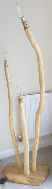
| Now to choose the shades (May 2022). |
This has been a long project and I've learned a lot about the construction. The cleaving, insertion of the wire and glueing worked very well and dried over two months with only one or two very minor splits (not on the glue line). Some of the poles cleaved easier than others so it is a good idea to have a few in reserve to choose from after they've dried. I found both hazel and ash did not cleave as easily or cleanly as the sycamore pole (first lampstand described above) but I haven't done enough work to generalize about this. In particular the slow grown hazel that I used was twisted which makes a curvy stand but at the same time the cleaving is more difficult.
The mounting of the stands on the base using the cylindrical tenons with shoulders was also easy and effective as was the routing for the electrical connections. I did try to make the hazel and ash wood darker with shellac and also aniline dyes but the results were not good and gave the appearance of a synthetic finish. I found that the best way to show-off the natural features of the woods was using a finishing oil, in my case dutch oil, using several coats. The ash pole had a lot of figuration and looked good as did the longer hazel pole. The shorter hazel pole had very little figuration and was similar to the single sycamore lampstand that I made first. The only drawback of using the local ash and hazel was that the light colour of the woods made the glue joints more visible than if I'd used a darker wood such as sweet chestnut. You're always going to be able to see some evidence of the glue line but I expect using darker woods that split cleanly would be easier. However, I found the light wood with figuration also has an attraction and fitted well with the sycamore base. The choice of lampshades is also crucial to the appearance. Drum type shades fits the shape of the stands.
Lampshades
We decided on drum style lampshades but had to experiment with the sizes. To do this we bought lampwires and made shades with brown paper to try different lampshade heights.
 |
| The final selection chosen to get a balance of sizes without the bulbs visible. The small one was 19 cm high and 62.8 cm in circumference, the next was 18 cm high and 62.8 cm in circumference and the largest was 24 cm high and 78.5 cm circumference. |
We used self-adhesive lampshade backing with an orange fabric to make the shades. Our method was basically:
1. Mark out the backing and cut to size. The backing needs to be the length of the circumference plus 1 cm for the overlapping join and the exact width the same as the height of the shade height.
2. Cut out a the fabric so it is something like 5 cm oversize on length and width. Then we marked a square corner and used a 1 metre straight edge along the length and width to mark the position of the backing. We used a chalk pencil to do this.
3. The next step was to lay the backing on the reverse of the fabric. The backing is self-adhesive and it is tricky to align it exactly to the two pencil lines. Starting at the "flush end", the backing was carefully laid using a plastic set-square to apply pressure to the backing to get adhesion and avoid any crinkling of the fabric. The fabric was folded back 1 cm at the other end using double-sided 1 cm width tape and another width of tape laid on top but without removing the protection backing. This is the tape that will form the join when the drum is completer.
 |
| Plan of the fabric and backing adhesive. The shading is the backing adhesive. The fabric was cut after applying the backing adhesive. The fabric was 1 cm wider at the bottom and top to allow folding over the lampshade frame. The fabric length was longer than the adhesive by 1 cm to permit folding and also slightly wider (about 3 mm) at one end to assist when joining the seam. |
4. After the fabric was laid, the edges of the fabric were cut to the pattern shown above. The lampshade rings were than made ready by applying a 1 cm strip of self-adhesive and fitting it around the wire. They were then rolled onto the backing where it joins the fabric making sure the wire was in contact with the backing and not the fabric.
5. The lampshade was joined using the preinstalled 1 cm tape and the top and bottom of the tape finally curled around the wire being careful to tuck the fabric under the wire.
 |
| Finished lampstand. |