Tuesday, March 23, 2021

Wooden Bar Clamp

 I couldn't find any complete examples of wooden bar clamps that used wooden screws for tightening.  However, I've seen a few examples of modern bar clamps that use steel threads with wooden bars etc.  The project started when I had a piece of partly dried sycamore that I could use to make a screw and some left-over ash and beech pieces. However, both the ash and beech needed to be ripped to size and for this I used my frame rip saw that I had recently made. It was a good opportunity to try the saw and in fact I soon found that the rip blade needed sharpening and the kerf adjusted as it was too wide. The saw then worked well as it cut straight without difficulty.

Screw spindle ready for threading. This was made using a branch of sycamore turned on the pole lathe.

The stock pieces ready for planing. The bar is ash and the arms are dried beech. The tightening spindle has been threaded (1/2 inch). 

My plan is to make a through mortice on the left-hand sliding arm and a through mortice and tenon attaching the right-hand arm to the ash bar. The first stage was to plane the stock to size. The bar was 53 x 23 x 545 mm and the arms 18 x 3 x 5 mm after planing with the hole for the screw 35 mm from the top of the arm. The sizes were mainly determined by the sizes of stock I had available but large enough to provide sufficient strength.

One side of the clamp fitted with the screw spindle threaded (3/4 inch) and the through mortice for moving the arm completed.

The spindle was threaded in the usual way after soaking for 2 days. The through mortice was firstly drilled through with a No 10 auger (drilling from both sides) and then finished by chiselling. Care was needed to ensure a tight fit and to do this the final adjustments to the arm and mortice were done using the joining plane (for the arm) and fine wood file for the mortice. A small chamfer was planed on each corner of the arm. I had considered making the top and bottom of the arm rounded but decided against this as it could jeopardise the fit of the arm. 

Showing the through mortice and tenon on left with dowels through and the moving arm with locators.

I made the mortice and tenon a very tight fit with dowels through and then drilled 5/16 th holes for the oak dowels into the beech arm. I then used these holes to position holes in the ash bar. Care was needed to get the holes in line when drilling with a brace and bit. Final adjustments were made with a round file. 

The end of the screw spindle was fitted with a pressure plate with a gaiter to allow the screw to be turned without the plate turning. This is a similar method to that I used in making the small wooden clamps. Small 6 mm dowels were used in a channel in the screw (as shown below) that was cut in the spindle on the pole lathe. After treating the threads with wax, this seems to be working well.

Details of the gaiter. The two 6 mm dowels are not shown

The finished bar clamp.
Two oak pegs are used to locate the moveable arm on the bar and in addition, a threaded hole was made on the fixed arm as shown. The threaded spindle can be easily removed by pulling out the two dowels in the pressure plate (they are a friction fit and not glued), unscrewing the spindle and then relocating it as needed. 
I am not sure how this can be improved, no doubt I will discover with repeated use! (any ideas will be welcome). I did notice a little movement on the moveable arm when a lot of pressure is applied using the screw even though the arm has no play when the locating pegs are installed. I don't think this will  be a problem as the movement is very small but I have noticed on one design that a small wedge was knocked into the top of the moveable arm to prevent the arm being pushed from the vertical.

Overall, this is a tricky job because of the need to get a strong joint on the fixed arm and tight fit on the sliding arm to the bar. I managed this and was pleased with the fit. I expect the use of a pillow drill would make the process easier but I like my augers and brace too much!!


Wednesday, March 10, 2021

Folding Frame Saw - Buck saw / Bow Saw

 I have made buck saws before and one that was easily folded to conceal the saw blade teeth. I have used oak and beech wood but for this I am using dried ash because I have some available. Also my previous folding saw used a 21 inch blade but this time I am trying a longer 24 inch greenwood blade.

This is the first saw I made, and the one I use now but it isn't a folding saw so needs to be taken apart for transporting.

None folding saw I made first. The arms are longer than the folding saw and enable a larger gap between the blade and the stretcher. This saw is made of oak from our kitchen cabinets in Dorset.
This is the first folding saw I made and gave to Emily. Again this was made from the kitchen oak cabinets and has served her well on her travels.

The folding saw ready for travelling. The saw teeth are protected and held so they can't damage anything when transported. I used hemp cord that lasted several years before it had to be replaced.

This frame saw is longer and uses 600 mm blades from Dieter Schmid Fine Tools (fine-tools.com). The arms are beech and the stretcher was made of oak as above. The handles were turned from beech and the cord is replaced by a 6 mm threaded rod with a wing-nut for tightening. I have a rip, cross-cut and turning blade that fits this saw.

Ash wood folding saw.

Anyway, onto the new saw. I started by planing a piece  of  ash stock to 22 x 50 x 660 mm to make the two arms. Next I cut a slot to accommodate the blade as the arms fold down over the blade. The blade is 20 mm deep so the slot needs to be about 22 mm deep and cut in the centre.

At this stage the arms are still in one piece as the groove down the centre is cut with a  plough plane fitted with a 1/8 th inch blade.

The plough plane (Record 044) didn't allow me to get to the required depth of 22 mm so I deepened the groove with a large rip saw. This was easy as the groove cut with the plough was already over 1 cm deep. I think this method is better than using two pieces of rebated wood glued together, the method I'd used before to make the grooved arms. Next I positioned the blade with the longest hole 15 mm from the inside edge of the arm and 34 mm from the end of the bottom of the arm, marked and drilled from each side. I then bolted one end of the blade into the arm and marked the position of the second hole for mounting the blade (the holes were 584 mm apart). This left about 5 mm of waste at the end of the arm. After drilling the second mounting hole, the centre was measured and cut. To enable the blade to rotate in the mounting, a small concave was cut in the groove under the mounting bolts using a small chisel.

The arms were then shaped semi- circular (about 2.5 cm diameter) at the top and bottom  using a coping saw, spoke shave and wood file. Also a small semi-circular indent (2.5 cm diameter and 1 cm deep) was cut very near the top of each arm to fit the tensioning cord.

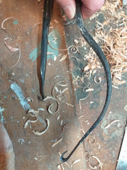
The arms connected to the blade. The arms fold down to cover the teeth for transporting the saw, Further work will be done to shape one arm for hand grip and chamfering edges

Having prepared the basics for the arms, I planed some ash stock down for the stretcher to 31 x 24 x 612 mm and cut some arched tenons on each end. These were 30 mm long with an arch of 15 mm radius as shown in the photo. These were  cut in the normal way with a tenon saw and the curved shoulders shaped with a fine chisel. The mortices were cut with the saw channel running through the centre and going 1 cm deeper. They were shaped to allow some movement in the joint.

The shape of the tenon to allow movement of the arms during tensioning the saw blade

The joint ready for final preparation;  joint must allow some movement of the arms

The rest was straight forward, rounding edges, marking the tenons and I did some relief carving of an  ash leaf and then I treated with linseed oil and wax.

Finished frame saw for Rebecca with some decoration and pyrography to show matching tenons. I used 2 mm twisted hemp cord to tighten.

This is the saw folded and ready for transport. All it needs is a custom carrier bag!

 This frame saw was a little more tricky to get flat when tightened and I think this is because of the relatively narrow stretcher compared to my other saws shown at the beginning. Also ash is a lighter wood compared with oak and so ideal for carrying, it may prove less resilient, only time will tell.

 I noticed when I was visiting Sweden that some of the older frame saws were made differently. The stretcher went through the arms via a through mortices but the blade was tightened in the same way. I can see that this method as the advantage of perhaps being able to move the stretcher up and down the arms although some were held in position with a dowel (or peg) swivels through the arms. The blades were longer and wider and I guess designed for farming use on large timber; they looked pretty robust!

A selection of old frame saws seen in Stockholm. Some of the stretchers are attached differently from mine.

This saw is from a Spanish Naval Museum and is of a form described by Henry C Mercer (Chinese frame saw) without discreet handles. The blade is shaped at each end and held in place with iron bolts that can be turned to angle the blade if needed. I haven't seen this shape of blade before.

Another Spanish saw with a narrow blade (also shaped at the ends) and I think with wooden stems to hold the blade. The arms on both saws are slightly curved for some reason. 


Sunday, February 21, 2021

Rip Frame saw of the style mentioned by Roubo

 I have some left over beech from projects and have been thinking of making another style of frame saw that dates back to medieval times and before. This is now commonly called a Roubo frame saw and there are some kits available in the USA and also in Europe. However, I decided to try and make one from wood without the ironware commonly used to attach the blade to the arm of the saw.  A larger version of the saw is also called  a "Framed Pitsaw" in the book by Henry C. Mercer (1929) "Ancient Carpenters' Tools" used to saw planks in saw pits and the like.

My design was determined by the blades that I have available for my existing frame saw which includes a rip and turning saw blades (distance between mounting holes is 580 mm) and the beech timber.  Also my aim was not to make something similar to those used by the sawyers in saw pits in the past but something more modest that one person could use with comfort to rip-saw a piece of timber. I basically made my own design as I will describe below.

Cutting an arm with a large frame turning saw.

The first step was to cut an arms (historically termed the "head sills") to shape from a block of kiln dried beech. I used my large frame saw fitted with a turning blade and for the tight bends went to a 10 inch frame turning saw. I finished off the shape using a block plane and small spokeshave. The maximum width of the arm was 7 cm, length 48 cm  and  9 cm deep. 

The next stage was to make the torsioner block (I'm not sure what this is called) which contains the screw spindle that tightens the blade. In earlier designs mentioned by Mercer, the blade was tightened by using a wooden wedge rather than a screw. The torsioner block had a large mortice cut to fit the arm, i.e. the arm fits through this mortice. One problem with using wood for this (these are now mostly iron) is that the grain of the wood needs to be parallel to the blade for strength. However this means that the screw spindle would go into the end grain and so produce weak threads. The threads need to be cut across the grain so a 4 cm thick piece of beech was glued to the end of the block and a 5/8 inch hole drilled through this and a further 2 cm of end grain into the centre of the mortice. Overall the block was 6.5 cm wide, 18 cm long and 7 cm thick in which a 3 cm by 7 cm through mortice was cut by drilling and chiselling. A 3 cm long tongue was cut to clasp the rip blade.  

One arm (or head sill)  complete ready for stretcher mortices.

Drilling the 5/8 inch hole for threading the screw spindle. Guide strips were used to get the auger central and a spirit level to make sure it was horizontal.

After the hole was drilled for the spindle, the thread was cut with a 3/4 inch die. A spindle was cut on the pole lathe using a piece of ash and threaded.

Arm and torsioner block with the screw tensioner in place. 

The strecher bars (3 cm x 3 cm) were joined to the arms using 3 cm by 1 cm tenons. Historically these bars are called "side strakes" and could be several feet long. Their lengths were matched with the blade in place so that the screw tensioner was just engaged with the arm that gave about 2 cm of adjustment. Care was taken to ensure arms (or side strakes) were parallel and that the arms and strechers were at right angles. The frame must be flat. A coin was placed where the screw tensioner contacted the arm and for the opposite block a small 1 mm channel was cut to locate it in the centre of the arm.

The frame after glueing ensuring that the frame is squared and is in a horizontal plane, i.e flat.

The final steps were to tidy the frame and treat with linseed oil ready for use.
Finished frame saw with blade installed and taut.

Frame saw in use
I have now used the saw several times to cut veneers and also some slats from hardwood as shown in the photo above. I used the kerfing plane (described in this blog, the second version with a coarser blade) to mark the saw cuts and then clamped as shown to saw down the lines with a rip blade installed. This worked well but needed good support and clamping when cutting long thin slats of wood. Generally I have found using the saw made ripping easier as you use both arms and a balanced position to saw long cuts.

A wider frame saw seen in a Naval Museum in Spain. This is slightly longer than my saw and also wider. The blade is attached by iron fittings. The blade is also curved at each end similar to that shown for the Spanish bow saws.


Wednesday, January 13, 2021

Small soap bowl turned from ash

 I have turned a couple of soap bowls using ash greenwood and also carved some rectangular ones. I thought I'd just remind myself of the process as we needed a couple more bowls.

I started with a log of spalted ash and sawed, chopped and chiselled a blank as usual. The wood was hard and not the easiest to turn but it all adds to the experience. I adjusted the arm rest on the lathe to get the tool in a good position and also released some tension on the bungy cord (it was taut because the previous job had been a large hefty bowl which needed a bit of muscle to turn). I attached a tenon mandrel and started turning the outside of the bowl and base including a plinth and concave shape as shown below.

Roughing out the outside with TU tool. The ash is spalted but hard.

I did the outside with a slight bulge around the centre.

Turning the centre was challenging because of the lack of space between the core and the inside. The photo shows the use of the cranked tool (double sided UP tool).
 
The inside of the bowl was  turned with the TD tool near the centre and then the TU to shape the rim and inside. I had the usual problem with the core but the cranked tool (as shown above) helped excavate the bowl. This was difficult because of the space between the core and inside of the bowl. I think I will make a smaller diameter mandrel for the small bowls as this will make the excavation easier.

When the inside was deep enough I decided to chisel the core out and release the mandrel. I guess this would be frowned on by traditionalists but to me it made sense not to risk damaging the bowl at this stage. This proved to be easy taking care to work across the grain when close to the base.

The soap bowl after finishing ( 8 cm diameter and 5 cm depth.)

After this I turned another soap bowl with another section of the spalted ash log but made this a wider diameter and shallow. I used the same tenon mandrel. This turned easier than the small deeper bowl shown above because access to the inside of the bowl was easier although removing the core was still very difficult and I need more practice with reducing the core to a small enough diameter to allow an easy break across the grain.

Larger diameter ash soap bowl (about 13 cm diameter and 3.5 cm depth)


Friday, January 8, 2021

Bowl turning on Pole Lathe- large ash bowl.

 I decided to try making another bowl on the pole lathe using a large ash log that had been felled last summer and left in the woods until removing in December (2020) and stored in my workshop until now. This is the largest bowl that I have tried (about 8 inches diameter) and I know that ash is not the easiest wood to use for bowls because of the "stringy" nature of the grain but I felt like a challenge especially as the wood had spalted and should produce some interesting effects that are totally unpredictable.

The start of the turning process on the outside.

The top of the bowl blank before turning.

The log was split in half and shaped for the lathe. This was difficult because the wood was hard and the final shape wasn't as good as I'd have liked. However, I made some final adjustments after starting the turning. A large mandrel was used and nailed into the blank. 

 I started by shaping roughly the outside with the TU tool and then the base with the TD and TU tools to produce a rim and a slight concave to the centre. The weight and size of the blank made the turning hard work but I knew this would get easier as the wood was removed !

After roughing the outside, the inside was started...a long way to go at this stage.

After some more turning the base is in sight. The rim and outside still need a lot of refinement.

As you can see, I kept the core diameter slightly larger than the mandrel so that I didn't risk breaking. From making other bowls I have always found it difficult to reduce the core diameter. I used the TD tool as much as possible to remove wood near the base of the core and in addition I now have a double edged cranked tool made by Ben Orford that makes excavation near the core easier but I found needs skill to use it - still working on that!

The  "cranked" tool on the right used to reduce the core

One change I did make was to lower the support arm on the lathe as I needed to work more at 6 to 7 OC and this was difficult with the arm high. I have made it more adjustable so that its vertical position can be changed according to the size of the bowl being turned. Ben Orford's videos on bowl turning were useful in judging the relative position of the bowl and arm.

I always find it difficult to judge the depth of bowls but this time I used a large caliper to get the sides about right; the bottom was more difficult but I tried for about 3/8 inch. I used the TD and TU tool to remove some of the core well below the nails of the mandrel. Use of the TD tool became impossible without scraping the rim of the bowl so I tried the cranked tool and it did do the job eventually but I need a lot more practice. The trick is to get the right angle but I kept snagging and when it did work, the sound wasn't pleasant. I sanded the rim and outside and burnished with shavings. Anyway when I got the core down to 1 inch diameter I used a chisel to reduce it a little further (scared of breaking the base) and then broke off the core across the grain.

The broken core still attached to the mandrel

The inside of the bowl after chiselling the remains of the core away. Some spalting and pink colouration evident on the wood.

The outside of the finished bowl. 

The base of the bowl showing the rim and concave base.

The bowl was dried slowly in a paper bag with shavings and then left in a cold workshop after coating with walnut oil.

A smaller bowl was also made from the same log of ash. This went straight forward and produced something that resembled a cereal bowl.
Another ash bowl ready for drying.

The last piece of the ash log was used to make a top for a steel jar and a small bowl. As always I had difficulty reducing  the centre core before breaking it off.


Reducing the centre core before breaking off. The ash was pretty dry having been in the workshop for about 18 months.

Small cereal bowl or similar. Not much sign of spalting on this section of the ash log. 

Side view of the same bowl  before treating with walnut oil.


Tuesday, December 22, 2020

Marking gauge with knife-edge.

 I don't have a knife-edge marking gauge only the pin type so I decided to try and make one following the method shown by Bob Rozaieski (https://brfinewoodworking.com).   It will be easiest if I show the finished gauge first and then go on to describe the construction.

The finished gauge showing the fence, arm and knife-edge.

I used kiln dried beech for the fence and arm and then some hardwood that I obtained from a pallet originating in India so I'm not sure what it is but I liked the colour and hardness. First I used some stock (3 inches by 2 inches and 1 inch thick) and measured out for three fences to make three gauges.

Stock for the three fences

I   drilled the 5/8 inch diameter holes for the arms centred 1 inch from the edge. I drilled these from both sides and then drew tangents to chisel a square base as shown. The top of the fence was shaped by scribing a 1 inch semi-circle centred 1 inch from the top and then using a coping saw to remove the waste and then shape with a carving file.

First stage on one of the fences. The fences were kept together until the main part of the woodwork was completed just because it was easier to handle them in the vice.

All the arm holes drilled and shaped ready to make mortices for the pegs

The next stage was to make the mortices for the holding peg. This was 1/4 inch wide and narrowed from 1/2 inch to 3/8 inch (slope of about 6 degrees).The mortice needed to enter 1/16 th inch into the arm hole on the straight edge of the hole so as to get a tight grip between the fence and the arm.. I did this by first filling the arm hole with a section of beech to prevent tear-out when using the chisel and then drilling a 1/4 inch hole close to the bottom of the  mortice (i.e. just above the straight edge). I then carefully chiselled out the mortice with a mortice chisel concentrating on the vertical side of the mortice and taking to about 3/8 inch wide. I then made the slope on the mortice working from the other side (1/2 inch width side). After removing the plug I made final adjustments to the mortice.  

It is difficult to describe making the tightening peg. I used some waste Indian wood, darker than beech and just as hard and planed a 11 cm piece to get the correct thickness (1/4 inch) and maximum width (1./2 inch). These were made to fit rather than to exact measurements. The slope was then cut with a carving knife / wood file and the ends shaped as shown below.

Tightening peg about 11 cm long and shaped to fit the mortice in the arm.

The fence, tightening pegs and knife edge. The knife edge was 1/4 inch wide and about 4 cm long and the holding peg about 4 cm long and 1/4 inch wide (sorry for the mixed units!1)

The fence was finished by putting a 1 cm x 1 cm  chamfer on the lower edge of the fence (on the side away from the cutter), and small (1 mm) chamfers on the edges of the fence. 

The arm was about 9 1/2 inches long (Bob makes his 8 inches I think) and 5/8 inches square and was planed  with the reference side (the flat side) at the bottom. The arm was planed and checked against the size of the hole. The curved side of the arm was shaped with a shoulder plane. This was done by marking the end-grains through the hole in the fence and then planing to the line being careful to check the fit and adjust by finally sanding to get a snug with no slack. This proved easier than I thought. I don't have a 5/8 th hollow plane to make it easier.

The cutting blade was made from a 1/4 inch strip of 001 steel about 4 cm long and shaped to a semi-circle cutting edge. This was held in place with another peg in a 1/4 inch sloped mortice made about 1 inch from the end of the arm. This was shaped as shown. 

The other two gauges were made in the same way but not separated until the mortices were finished.

Difficulties:  The construction is straight forward. Reference faces need to be good on the arm and fence so that all faces are at right angles and flat. The tightening pegs need to be made after the mortices and carved to fit. The mortice on the arm is tricky to make in particular to avoid tear-out when cutting the straight edge nearest the fence.

Three finished marking gauges for presents.


Friday, December 18, 2020

Large bulky mallet

 This was made from some spalted hawthorn wood for the head and ash for the handle. The head was turned on the pole lathe to get the shape I wanted that seemed to fit the wood. The wood was very hard and also pretty wet as it had been sitting outside since the summer but it did turn well.

Finished mallet after treating with linseed oil.

The ash was from the same tree that I made the picture frames from but this particular log was straight grained and ideal for this handle. I enjoyed turning this and finding different grip positions on the handle as I knew the mallet head was going to be big and heavy.

The end of the handle was turned to a diameter of 1 inch so that it could be fitted through the centre of the head. Drilling the hole for the handle in the head was tricky but proved straight forward by using the pole lathe centres to draw a line around the head and then drilling about half way from both sides. I had previously used the pole lathe and pencil to mark a centre line around the head. If you are practised with a traditional brace it is easy to get the holes to meet precisely. 

The handle was attached by glueing and placing a beech wedge across the grain of the handle and the head to reduce the chances of the wedge causing splitting.